

Cold Room Pressure Gauge: Complete Guide to Reading, Diagnosis and Buying
A cold room pressure gauge, also known as a refrigeration manometer (refrigeration pressure gauge), acts as the smart eyes of a vapor-compression refrigeration system. One look at the numbers on this instrument lets you quickly analyze the health of the cycle, the refrigerant charge, the condition of the expansion valve and the efficiency of the compressor. This complete technical guide gives refrigeration technicians and engineers all the key points: how to read LP and HP pressure, diagnostic tables, and a buying guide for manometers and manifold gauge sets.
What Is a Cold Room Pressure Gauge and Why Does It Matter?
In a vapor-compression refrigeration cycle, refrigerant pressure and temperature are directly linked by thermodynamics. This relationship is defined precisely by the pressure-temperature (P/T) chart. A cold room pressure gauge, also known in the industry as a refrigeration manometer, is an instrument that measures refrigerant pressure in different parts of the system and allows real-time monitoring of cycle health.
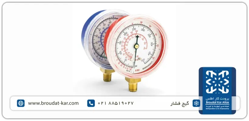
In all refrigeration equipment, two main pressure points must be monitored:
- Low-pressure (LP) gauge, suction side: measures the suction line, from the evaporator outlet to the compressor inlet. The reading corresponds directly to the evaporating temperature of the refrigerant in the evaporator.
- High-pressure (HP) gauge, discharge side: measures the discharge line, from the compressor outlet to the condenser inlet. The reading corresponds to the condensing temperature in the condenser.
In addition to these two points, industrial refrigeration systems also use other specialized gauges, such as the compressor oil pressure gauge (for the lubrication circuit pressure) and the differential pressure gauge on ammonia pumps and filters.
Any deviation from the normal range is an early technical warning. Catching it in time lets a technician start troubleshooting before it becomes serious damage, such as broken compressor valves or a burned-out motor winding. To see what happens when pressure is left unmonitored, read our article on cold room compressor failure: causes and solutions.
Types of Cold Room Pressure Gauges
Cold room pressure gauges are classified by installation type, internal mechanism, position in the cycle and the way they display readings.
1. Fixed Pressure Gauges: Dry vs. Liquid-Filled
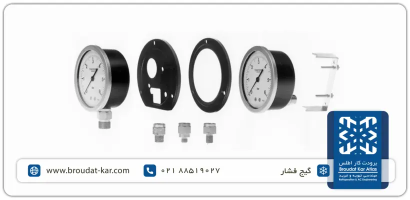
Fixed gauges are permanently mounted on the control panel, the compressor frame or the machine-room piping.
- Dry pressure gauge: the internal mechanism has no fluid around it. These gauges are cheaper, but in high-vibration locations (near compressors and pumps) the needle fluctuates heavily and mechanical wear is high.
- Liquid-filled pressure gauge (glycerin or silicone oil): the case is filled with glycerin or silicone oil. The fluid dampens needle fluctuation (damping), lubricates the internal parts and protects the gauge from heavy machine-room vibration.
| Liquid-filled pressure gauge | Comparison criterion | Comparison criterion |
| Suitable | Calm, vibration-free location | Calm, vibration-free location |
| Excellent (vibration resistant) | High-vibration location (on the compressor frame) | High-vibration location (on the compressor frame) |
| High and stable | Reading accuracy under vibration | Reading accuracy under vibration |
| Higher | Price | Price |
2. Gauges by Location and Function in the Cold Room
Besides the two main suction and discharge gauges, other specialized gauges sit at different points in the circuit:
- Low-pressure or suction gauge (LP gauge): records the refrigerant pressure entering the compressor, which corresponds to the evaporating temperature.
- High-pressure or discharge gauge (HP gauge): measures the refrigerant pressure leaving the compressor, which corresponds to the condensing temperature.
- Oil pressure gauge: shows the pressure in the compressor lubrication circuit. On compressors with an oil pump, the net oil pressure is the oil gauge reading minus the suction or discharge pressure, depending on the compressor type.
- Differential pressure gauge: installed across the inlet and outlet of ammonia (R717) pumps and oil-line filters to show the pressure drop, and therefore whether the pump is working properly or the filter is clogged.
3. Manifold Gauge Sets (Twin Gauges: The Technician’s Tool)
A refrigeration manifold gauge set is the portable, essential tool technicians use for charging refrigerant, pulling a vacuum and pressure testing:
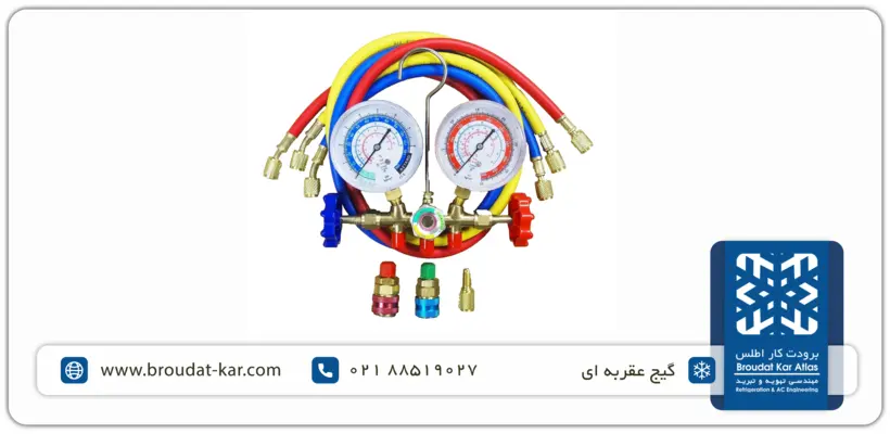
- Analog manifold gauge set: two dial gauges, three high-pressure hoses and a valve body. Needle flutter on an analog set can point to a mechanical problem such as liquid floodback or compressor valve trouble.
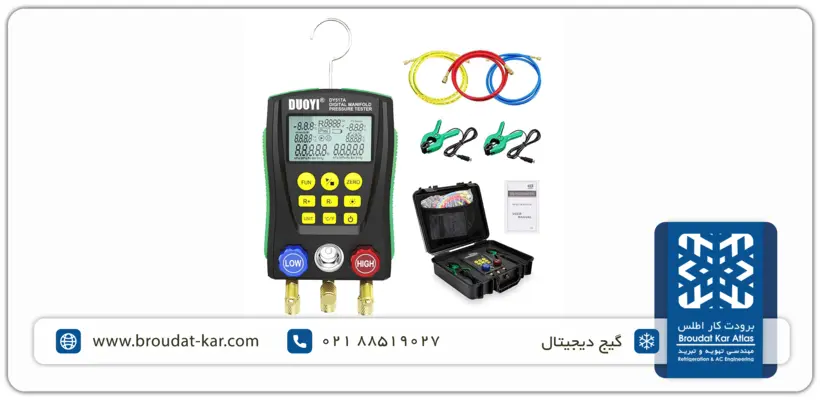
- Digital manifold gauge set: fitted with electronic pressure and temperature sensors. It calculates superheat and subcooling automatically and shows them on the display.
How to identify a gauge
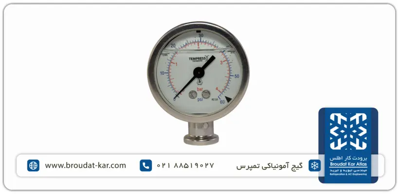
On industrial brands such as Tempress or WIKA, which have a plain stainless-steel or black case, the gauge type (suction, discharge or oil) can only be identified from the abbreviation and the pressure range (scale) printed on the dial.
How to Read a Cold Room Pressure Gauge: Step by Step
Reading the numbers on a gauge without thermodynamic analysis is just recording a few figures. To diagnose the cycle accurately, a technician has to convert the pressures to saturation temperature and calculate superheat and subcooling. Follow these steps in order to read the pressure correctly and analyze system performance:
Step 1: Connect the Hoses Correctly (Manifold Gauge Set)
- Connect the low-pressure (LP) hose to the compressor suction port or the evaporator outlet line (the larger-diameter pipe).
- Connect the high-pressure (HP) hose to the compressor discharge port or the condenser outlet (the smaller-diameter pipe).
Step 2: Let the Cycle Stabilize
After starting the cold room system, wait at least 15 to 20 minutes so that pressures and temperatures across the circuit reach relative stability. Reading the pressure right after the compressor starts leads to a diagnostic error.
Step 3: Record Suction and Discharge Pressure
Note the readings on both gauges in the system’s standard unit (usually bar or psi).
Step 4: Consult the Pressure-Temperature (P/T) Chart
Using the P/T chart for the refrigerant in the system (for example R404A or R22), convert each pressure reading to its equivalent saturation temperature:
- Suction saturation temperature (Tsat,LP): equals the LP gauge pressure and shows the refrigerant evaporating temperature.
- Discharge saturation temperature (Tsat,HP): equals the HP gauge pressure and shows the refrigerant condensing temperature.
Step 5: Calculate Superheat
With a calibrated thermometer, measure the actual suction line temperature (Tactual,suction) about 10 cm past the expansion valve bulb. Then use the formula below:
Superheat = Tactual,suction – Tsat,LP
- The standard evaporator superheat range is 5 to 8 °C. A superheat below 5 °C raises the risk of liquid refrigerant entering the compressor.
Step 6: Calculate Subcooling
Measure the actual liquid line temperature (Tactual,liquid) at the condenser outlet or just before the expansion valve, then calculate:
Subcooling = Tsat,HP – Tactual,liquid
- A standard subcooling of 4 to 8 °C indicates complete condensation and no vapor bubbles in the liquid line.
Normal Cold Room Pressure Chart (Primary Reference)
Operating pressure depends directly on ambient temperature and the type of refrigerant. The table below gives approximate normal pressure ranges for common refrigerants:
| Normal HP (discharge) range at 35 °C ambient | Normal LP (suction) range | Application / evaporator temperature | Refrigerant |
| 19.0 – 22.0 bar | 3.0 – 4.0 bar | Above freezing (evaporator about -10 °C) | R404A |
| 19.0 – 22.0 bar | 1.0 – 1.8 bar | Below freezing (evaporator about -25 °C) | R404A |
| 16.0 – 19.0 bar | 2.0 – 3.0 bar | Above freezing (evaporator about -10 °C) | R22 |
| 16.0 – 19.0 bar | 0.5 – 1.2 bar | Below freezing (evaporator about -25 °C) | R22 |
| 11.0 – 12.0 bar | 1.0 – 1.5 bar | Above freezing (evaporator about -10 °C) | R134a |
Engineering note
The values above are approximate and are based on a condenser designed for a temperature difference of 10 to 15 °C from ambient. Always use the manufacturer’s technical catalog as your reference.
Cold Room Fault Diagnosis Chart: Reading Suction and Discharge Gauges
Analyzing low-side (LP) pressure or high-side (HP) pressure on its own can lead to a wrong diagnosis. The key to accurate troubleshooting is to analyze the suction and discharge gauges together. The chart below is a practical troubleshooting reference based on how both gauge needles behave at the same time:
| Corrective action and troubleshooting | Probable causes and technical scenario | Discharge (HP) gauge | Suction (LP) gauge |
| Leak-test the circuit, repair the leak and recharge. Check the service valves and open them fully. | Low refrigerant charge (leak in the circuit). Liquid line service valve closed | Below normal | Below normal |
| Measure superheat (high superheat points to a restriction). Replace the filter drier, or service/replace the expansion valve needle. | Expansion valve needle stuck or clogged. Clogged filter drier or restricted liquid line | Normal or slightly low | Below normal |
| Recover the excess refrigerant and adjust the charge by subcooling. Wash and service the condenser fins. Check and replace the condenser fan. | Refrigerant overcharge. Dirty condenser or poor heat exchange. Burned-out or failed condenser fan. | Above normal | Above normal |
| Run a compressor compression test. Readjust or replace the expansion valve. | Weak compressor (failure or leaking valves). Expansion valve stuck too far open. | Below normal | Above normal |
| Recover the refrigerant, pull a full vacuum and recharge. Improve machine-room ventilation and clean the condenser. | Non-condensable gases (air left from an incomplete vacuum). High ambient temperature or a heavily fouled condenser. | Much higher than normal | Normal |
| Insulate the expansion valve bulb and clamp it firmly to the pipe. Fine-tune the expansion valve superheat adjustment screw. | Unstable expansion valve with severe hunting. Thermal bulb loose on the suction line. | Fluctuating | Fluctuating (hunting) |
| Check the control circuit and the cold room electrical panel. Test the contactor and the compressor winding. | Compressor is off. Power outage, tripped pressure switch or failed contactor. | Equal to suction pressure | Equal to discharge pressure |
| Immediate action: shut the system down to prevent broken compressor valves. Use a liquid-filled gauge to damp frame vibration | Liquid refrigerant floodback to the compressor. Severe mechanical vibration of the frame | Variable / unstable | Severe needle vibration |
For a closer look at the related components, read our complete guide to the cold room expansion valve to check refrigerant control faults.
Calibration and Maintenance of Cold Room Pressure Gauges
Even the most expensive and accurate refrigeration gauge gives a technician wrong information if it is poorly maintained or loses calibration, and that leads to costly misdiagnoses. To keep gauges accurate and extend their service life, follow these rules:
- Zero adjustment: before each use of a manifold or portable gauge, with the gauge disconnected from every port and at atmospheric pressure, the needle must sit exactly on zero. If it is off, set it to zero with the calibration screw on the dial or the back of the case.
- Periodic calibration: fixed panel- and frame-mounted gauges should be calibrated every 6 to 12 months, using a calibration device or by comparing them against a reference gauge.
- Cloudy glycerin: in liquid-filled gauges, fill fluid that turns yellow or cloudy signals moisture or contamination. The fluid should be replaced so the dial stays readable.
- Hose care: after charging or servicing, flush the manifold hoses with dry nitrogen to clear residual oil and refrigerant and keep moisture out of later jobs.
- Maximum allowable pressure: never use a low-pressure (LP) gauge for nitrogen pressure testing at high pressure (above 10 bar). Doing so permanently deforms the diaphragm or the Bourdon tube and ruins the gauge.
Cold Room Pressure Gauge Buying Guide
Choosing the right gauge depends directly on the application (fixed on the compressor frame, or portable for service work), the type of refrigerant and the level of vibration in the environment.
Reputable Gauge Brands on the Market
| Features and best use | Equipment type | Country | Brand |
| Highest accuracy, industrial stainless-steel case, ideal for permanent mounting on the compressor frame | Fixed (dry and liquid-filled) | Germany | WIKA |
| Extremely rugged case, suited to ammonia and heavy-duty industrial cold storage | Fixed industrial | Denmark | Tempress |
| Excellent quality, high vibration resistance, fair price | Fixed, liquid-filled | Italy | Italmanometer |
| Popular with professional technicians, durable valves and hoses | Manifold (analog / digital) | Switzerland | Refco |
| Smartphone connectivity, automatic superheat and subcooling calculation with high accuracy | Digital manifold | Germany | Testo |
| Economical options for general and semi-industrial use | Manifold and fixed gauges | China / Taiwan | Value / Nurbrodut |
Buying warning
Avoid cheap, unbranded gauges for permanent installation on a compressor. Their inaccuracy when reading oil pressure or discharge pressure can cause serious damage to the compressor.
Conclusion and Expert Advice from Broudat Kar Atlas
Accurate pressure monitoring is the simplest and, at the same time, the most effective way to ensure the long-term health of a cold room and prevent sudden production line stoppages. In all cold room construction and service projects, Broudat Kar Atlas engineers use calibrated European measuring instruments and gauges to set superheat and subcooling precisely.
To receive expert advice, periodic cold room troubleshooting or calibrated refrigeration equipment, contact our specialists.