


Cold Storage Heat Load Calculation — Complete Engineering Formula Guide
Accurately calculating the refrigeration load for a cold storage facility is the single most critical step before purchasing any refrigeration equipment. An undersized system fails to reach target temperature; an oversized one wastes capital and energy. An error in insulation U-value, product load, or air infiltration estimate can overload the compressor, spoil stored goods, and shorten equipment life. This guide covers both the full engineering method and the quick rule-of-thumb approach, with worked numerical examples.

What Is Refrigeration Load (Heat Load)?
Refrigeration load — also called cold room heat load or cooling load — is the total rate of heat gain that the refrigeration system must continuously remove from the cold storage space per unit time (typically expressed in kW or BTU/hr) in order to maintain the target temperature and humidity.
An essential engineering distinction: refrigeration load and compressor capacity are not the same value.
- Refrigeration (heat) load: Result of the thermal calculation of the room and stored product.
- Compressor capacity: Derived from the heat load, then adjusted for pipe losses, defrost downtime, and a safety factor.
Refrigeration Load Unit Conversion Reference
| Common Usage | Standard Equivalent | Unit |
| Europe, Iran, engineering calculations | SI base unit | Kilowatt (kW) |
| Commercial reference in the US and Iranian market | 1 TR = 3.517 kW | Ton of Refrigeration (TR) |
| Legacy equipment catalogs and small systems | 1 kW ≈ 3,412 BTU/hr | BTU/hr |
Four Sources of Heat Gain in a Cold Storage Facility
All thermal energy entering the cold storage space must be identified and quantified. These gains fall into four categories:
| Typical Share of Total Load | Mechanism | Heat Gain Source |
| 30 – 50% | Conductive and radiant heat transfer through walls, ceiling, and floor | Wall / Transmission Load |
| 20 – 40% | Sensible heat removal from incoming product; freezing latent heat; respiration heat | Product Load |
| 20 – 40% | Warm, humid outside air entering on door opening | Infiltration Load |
| 10 – 20% | Lighting, evaporator fans, personnel, forklifts, defrost heat | Internal / Misc. Loads |
Step 1 — Wall (Transmission) Load
Transmission load results from temperature-driven heat conduction through the insulated panel envelope: walls, ceiling, and floor. It is calculated using the standard heat transfer formula:
Q_wall = (U × A × ΔT) ÷ 1000 [kW]
- U: Thermal transmittance of the insulation panel (W/m²·°C). Lower U = better insulation.
- A: Total surface area of all four walls + ceiling + floor (m²).
- ΔT: Design outdoor temperature minus design indoor temperature (°C).
U-Value Reference — Polyurethane Sandwich Panel
| Typical Application | Approx. U-Value (W/m²·°C) | Panel Thickness |
| Above-zero cold rooms (chilled storage) | 0.22 | mm 100 |
| Below-zero freezers and blast freeze tunnels | 0.15 | 150 mm |
| Below-zero freezers and blast freeze tunnels | 0.11 | 200 mm |
Worked Example — Wall Load
Cold room: 10 m × 8 m × 4 m (L × W × H). Panel: 100 mm PU (U = 0.22). Location: Tehran. Design indoor: −18°C. Design outdoor (peak summer): +40°C.
A = 2(10×8) + 2(10×4) + 2(8×4) = 160 + 80 + 64 = 304 m²
ΔT = 40 − (−18) = 58°C
Q_wall = (0.22 × 304 × 58) ÷ 1000 = 3.88 kW
☀️ Solar Radiation Correction: For south- or west-facing walls and roofs in direct sunlight (especially dark-colored surfaces), add 5–11°C to ΔT for that surface only. In hot climates this can add 10–15% to the transmission load and should never be omitted.
Step 2 — Product Load
Product load accounts for the thermal energy that must be extracted from the goods entering the cold room. For freezer storage, this includes three sequential phases that must all be calculated:
| Description | Formula | Phase |
| Cool product from entry temperature down to freezing point | Q₁ = m × Cp_above × (T_in − T_freeze) ÷ (t × 3600) | Sensible cooling above freezing |
| Remove latent heat of fusion at the freezing point (~334 kJ/kg for water-rich products) | Q₂ = m × L_f ÷ (t × 3600) | Latent heat of freezing |
| Cool frozen product to final storage temperature | Q₃ = m × Cp_below × (T_freeze − T_storage) ÷ (t × 3600) | Sensible cooling below freezing |
⚠️ Critical: For products entering above 0°C that must be frozen, the latent heat of fusion (Phase 2) is typically the single largest load component and is frequently omitted in preliminary estimates. This omission causes severe under-sizing of the compressor.
For chilled storage (above-zero rooms), where product enters close to storage temperature and is not frozen, only sensible cooling and respiration heat apply:
Q_product = (m × C × (T_in − T_storage)) ÷ (t × 3600) [kW]
- m: Daily product intake (kg)
- C: Specific heat above freezing (kJ/kg·°C) — see ASHRAE table below
- T_in / T_storage: Entry and final storage temperatures (°C)
- t: Pull-down time in hours (typically 16–24 h)
Thermal Properties of Common Cold-Stored Products (ASHRAE Reference)
| Storage Temp (°C) | Latent Heat L_f (kJ/kg) | Cp below freezing (kJ/kg·°C) | Cp above freezing (kJ/kg·°C) | Product |
| 18- | 250 | 1.68 | 3.52 | Beef (frozen) |
| 18- | 246 | 1.77 | 3.35 | Chicken (frozen) |
| 23-18-to | 276 | 2.05 | 3.60 | Fish (frozen) |
| to+1+4 | – | – | 3.60 | Apple (fresh) |
| 0 to +2 | – | – | 3.92 | Carrot (fresh) |
| 0 to +2 | – | – | 3.43 | Potato (fresh) |
🌿 Respiration Heat (fresh produce only): Live agricultural products continue to respire after harvest and release heat continuously. For example, apples at +4°C generate approximately 30–40 W/tonne of respiration heat. This must be added to the product load for above-zero fresh-produce rooms.
Step 3 — Infiltration Load (Air Exchange)
Every door opening allows warm, humid outside air to enter and displace cold, dense inside air — creating both a sensible and a latent (moisture) heat load on the refrigeration system.
Q_air = (V × N × ρ × (h_out − h_in)) ÷ 86400 [kW]
- V: Internal volume of cold room (m³)
- N: Number of complete air changes in 24 hours (see table below)
- ρ: Air density ≈ 1.2 kg/m³
- h_out − h_in: Enthalpy difference between outside and inside air (kJ/kg)
- 86400: Seconds per day — converts daily heat gain to continuous kW rate
Air Change Rate (N) by Room Volume — ASHRAE Reference
| Traffic Class | Traffic Class | Room Volume (m³) |
| Very small, frequent access | Very small, frequent access | < 15 |
| Small commercial | Small commercial | 15 – 50 |
| Medium commercial | Medium commercial | 50 – 100 |
| Large industrial | Large industrial | > 100 |
Infiltration Reduction Measures
- PVC Strip Curtains: Transparent PVC strip curtains reduce cold-air escape during personnel access.
- Air Curtain: Air curtain (air door): creates a high-velocity air barrier across the door opening.
- Dock Shelter / Loading Bay Seal: Dock shelter: seals the gap between the delivery vehicle and the cold room door.
- High-Speed Doors: Rapid roll-up doors that minimize open time during forklift traffic.
Step 4 — Internal & Equipment Loads
Heat sources inside the cold room add directly to the refrigeration load, regardless of the envelope or product:
- Material Handling Equipment (Forklifts, Pallet Trucks): Electric motors on forklifts and pallet trucks convert nearly all input electrical energy to heat inside the cold room.
- Evaporator Fans: Evaporator fan motors run continuously inside the room, converting essentially all their electrical input to heat that must be removed by the refrigeration system.
- Defrost System Heat: Electric-defrost heating elements or hot-gas defrost circuits release heat — a portion of which enters the room air rather than melting frost and must be accounted for.
- Lighting: Even LED industrial lighting releases heat proportional to wattage × operating hours. Motion sensors or timers reduce this load.
- Personnel: Human body heat in a cold environment is substantial: each worker performing physical activity in a below-zero room generates approximately 250–300 W. Operating hours and headcount both matter.
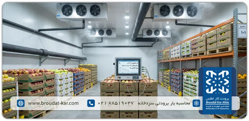
Rule of thumb: Internal and miscellaneous loads typically contribute 10–20% of the sum of transmission + infiltration + product loads. Use this to cross-check detailed calculations.
Total Load Calculation & Compressor Sizing
Sum the four calculated loads and apply a safety factor to cover unexpected conditions, equipment aging, and extreme weather events:
Q_total = (Q_wall + Q_product + Q_air + Q_internal) × 1.10 to 1.15
Then convert the daily load to a compressor capacity rating, based on effective daily running time:
| Reason for Limit | Compressor Effective Daily Run Time | Cold Room Type |
| Reserve time for defrost cycles and peak load buffer | 18 – 20 hours/day | Above-zero chilled storage |
| More frequent and longer defrost cycles required | 16 – 18 hours/day | Below-zero frozen storage |
Compressor Capacity (kW) = Q_total_daily (kWh) ÷ Run Hours per Day
Quick Rule-of-Thumb Estimation (Preliminary Sizing)
In early design stages or for rapid budgetary estimates before a full heat load calculation, engineers use volumetric load factors:
| Rule-of-Thumb Load Factor | Operating Temperature | Cold Room Type |
| 15 – 20 W/m³ | −18°C to −25°C | Below-zero frozen storage (large) |
| 60 – 70 W/m³ | +2°C to +5°C | Above-zero chilled storage |
| 100 – 150 W/m³ (product-dependent) | −30°C to −40°C | Blast freeze tunnel |
Example — 2,000 m³ frozen storage room at 15 W/m³:
Q_quick = 2,000 × 15 ÷ 1,000 = 30 kW (approximate)
⚠️ Important: Rule-of-thumb estimates are suitable for preliminary budgeting only. Equipment procurement must always be based on the full four-component heat load calculation above.
Specialist Software for Cold Storage Heat Load Calculation
Note that commonly referenced programs such as Bitzer Software and Danfoss Coolselector are equipment selection and cycle analysis tools — used after the room heat load is already known. For calculating the room heat load itself, the following specialist tools are used:
- LU-VE Cold Room Calc: Free mobile app by LU-VE specifically designed for cold room heat load calculation. Takes dimensional parameters, climatic conditions, insulation specification, and product entry conditions as inputs.
- Cold Room Calc: Dedicated cold room heat load calculation software providing a full breakdown by component (wall, infiltration, product, internal loads) and final load output in kW. A paid license is required.
- HICOOL / EngicalcHub Online Calculators (free): Web-based tool referenced by ASHRAE sources that calculates transmission, infiltration, product pull-down, and internal loads with unit-conversion output in kW, BTU/hr, and tons of refrigeration.
Equipment Selection Checklist Based on Calculated Heat Load
Once the total cold room heat load is confirmed in kW, equipment can be specified. Errors at this stage cause under-performance, excessive energy use, or premature failure:
- Compressor: Compressor capacity must be selected at the correct evaporating temperature (SST — Saturated Suction Temperature) and condensing temperature (SCT). Never select from rated capacity at standard conditions without de-rating for actual SST/SCT.
- Evaporator: Evaporator coil capacity must match the room heat load. Fin spacing for below-zero rooms should be 7–10 mm (to accommodate frost buildup); above-zero rooms use 4–6 mm spacing.
- Condenser: Condenser heat rejection capacity equals the evaporator load plus the compressor input power. For air-cooled condensers, de-rate based on local peak wet-bulb/dry-bulb temperature.
Engineering Consultation — Broudat Kar Atlas
Refrigeration load calculation is a multi-variable engineering process where accuracy in insulation coefficients, product entry conditions, and air infiltration estimates directly determines equipment life and long-term operating cost. Small errors compound into significant compressor overloading, product spoilage, and unplanned downtime.
Broudat Kar Atlas engineers, with decades of experience across large-scale industrial and food-cold-chain projects across Iran, provide precise refrigeration load calculations, energy audits, and complete refrigeration cycle equipment supply.
📞 Free Engineering Consultation & Project Quotation: +9821 88303600